Why ISBM Defects Are Harder to Diagnose Than SBM
In a two-stage reheat stretch blow molding process, the preform is manufactured separately and reheated before blowing. This separation means injection problems and blowing problems have distinct, traceable origins. In single-stage ISBM, there is no such boundary. The preform goes directly from injection to conditioning to stretch-blow within a single continuous cycle — meaning a melt temperature set 5°C too high at Station 1 can produce a cloudy sidewall discovered only after Station 4 ejection.
This cross-station defect propagation is the defining diagnostic challenge of ISBM. The 8 defects documented in this guide represent the most common failure modes encountered in PET bottle production on single-stage machines. For each defect, this article provides: a precise description of visual and dimensional symptoms, the verified root causes, quantified process parameters to investigate, and a step-by-step corrective action sequence.
Always trace a defect upstream before adjusting the blow station. In single-stage ISBM, 60–70% of blowing-stage defects originate at the injection or conditioning stage. Adjusting blow parameters to compensate for a root cause in the injection unit will mask the symptom while allowing material degradation to continue accumulating.
Pearlescence & Haze — Why Your ISBM Bottles Look Cloudy
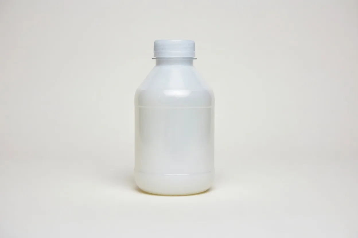
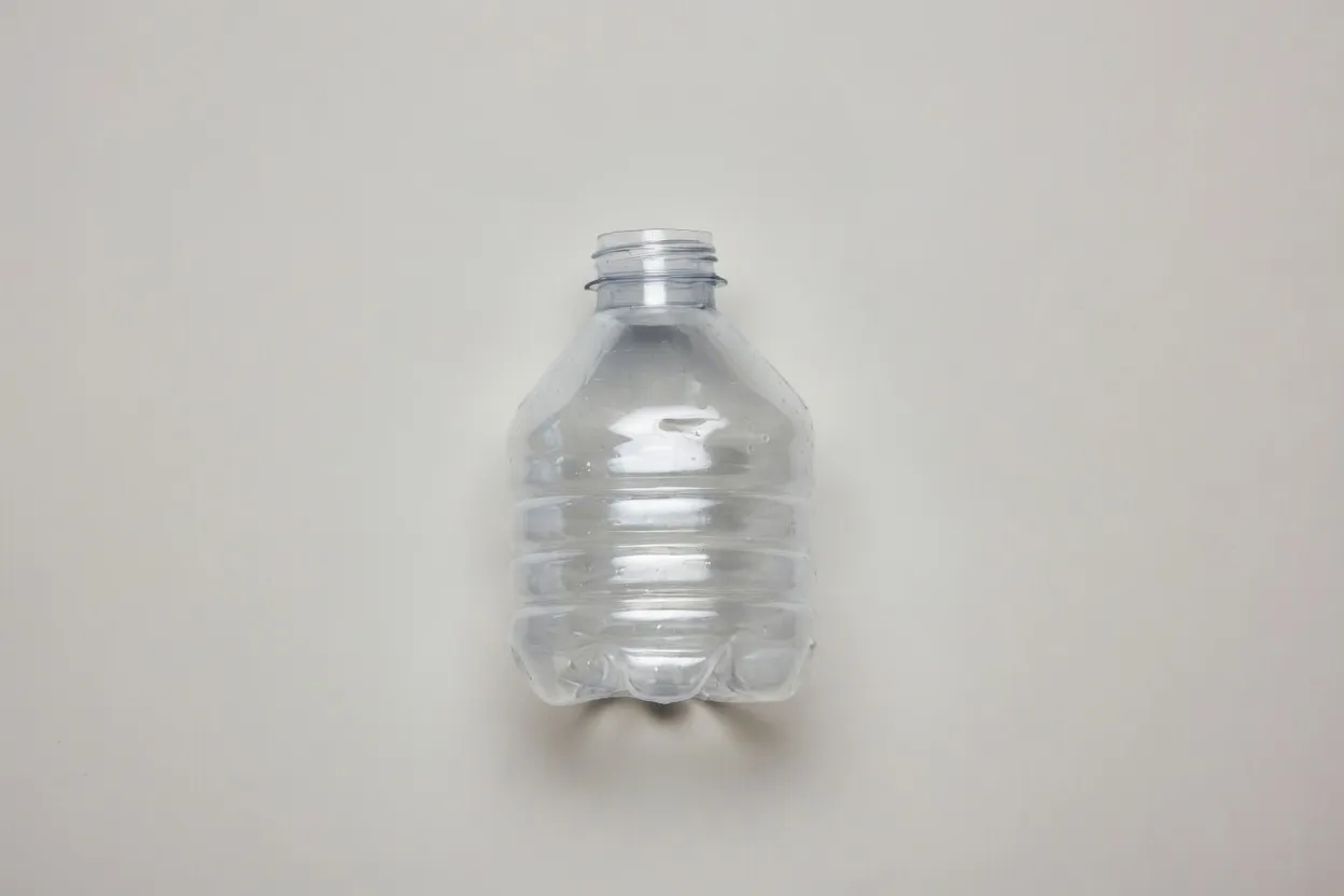
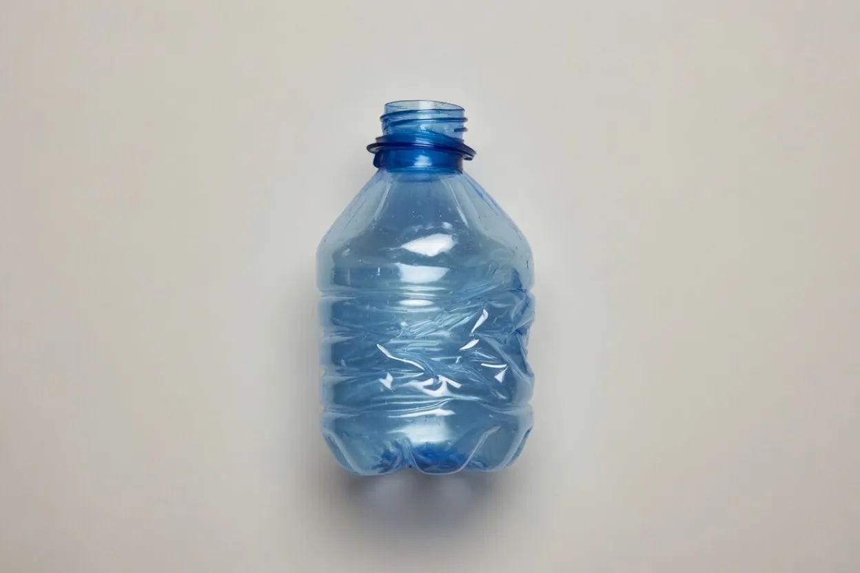
Pearlescence is one of the most frequently encountered ISBM defects and is visually unmistakable: the finished bottle develops a milky, opaque, or whitish appearance — typically in the shoulder and upper sidewall — that is absent from the preform. Transparency is severely reduced. In carbonated beverage applications, this is an immediate disqualifying defect.
The physical mechanism is well understood. PET is a semi-crystalline polymer with a glass transition temperature (Tg) of approximately 80°C. Successful stretch blow molding requires the preform to be heated above Tg into the orientation window (95–115°C) before blowing. Within this window, the amorphous polymer chains stretch and lock into a highly oriented, transparent structure. If the preform temperature is too low, the polymer is partially crystalline at the point of stretching — the growing microcrystals scatter visible light, producing the characteristic pearlescent haze.
- →Preform core temperature below 95°C at blow station entry
- →Blow delay too long — preform cools below Tg before stretching
- →PET IV value below 0.76 dL/g — insufficient chain mobility
- →Inadequate drying — residual moisture accelerates crystallisation
95–115°C
≥0.76 dL/g
160°C / ≥4h
10–15°C
Use an IR thermometer to measure preform surface temperature at the blow station entry. If below 100°C, incrementally raise conditioning heater temperature by 2°C per cycle and recheck.
If haze persists after temperature correction, request IV certificate from resin supplier. Values below 0.76 dL/g require material change or pre-SSP treatment.
Verify drying equipment performance: confirm dew point at hopper outlet is ≤−40°C and resin residence time is ≥4 hours at 160°C. Replace desiccant beds if dew point is drifting.
Once the defect is resolved, record the corrected parameters on the process control card and lock them. Revisit if ambient humidity increases significantly (seasonal adjustment).
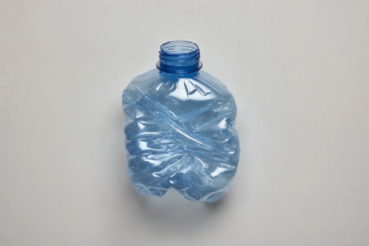
Wall Thickness Variation — Uneven Walls That Fail Drop Tests
Wall thickness variation manifests as a consistent asymmetry in bottle wall distribution — one circumferential sector measurably thinner than its opposite, an off-center shoulder, or a base that is thick on one side and thin on the other. The thin zone is mechanically vulnerable: drop tests will consistently fail at the thinnest point, and carbonated beverage bottles may develop stress cracking under internal pressure.
Critically, this defect has two distinct and separate origins that require different corrective actions. The first is a preform-level problem: if the preform itself has non-uniform wall thickness (a result of injection imbalance or hot runner temperature asymmetry), no stretch-blow process adjustment will create a uniform bottle. The second is a machine-level problem: a worn or eccentric stretch rod that does not travel centrally through the preform will create asymmetric stretching even from a geometrically perfect preform.
- →Preform wall eccentricity from hot runner temperature imbalance
- →Stretch rod worn, bent, or not concentric with preform axis
- →Asymmetric conditioning — one side of preform hotter than other
- →Preform not seated correctly in blow cavity (damaged locating pin)
≤0.05mm
±2°C
≤0.1mm TIR
<5% deviation
Diagnose origin first. Measure the preform wall thickness at 0°, 90°, 180°, and 270° using a calibrated ultrasonic gauge. If eccentricity exceeds 0.05mm, the problem is in the injection tool — proceed to Step 2. If the preform is symmetric, the problem is mechanical — proceed to Step 3.
Hot runner balance correction. Check individual zone thermocouple readings. Zones deviating by more than ±2°C should be recalibrated. Also check for blocked hot runner tips causing localised flow restriction.
Stretch rod inspection. Remove rod and check TIR (total indicator runout) on a V-block. Replace if runout exceeds 0.1mm. Check rod-to-preform clearance; excessive clearance allows rod to float off-center during travel.
Gate Blush & Stress Marks — Fixing the White Ring at the Base
Gate blush presents as a characteristic ring or starburst pattern of white, opaque, or glossy-differential material radiating from the injection gate point at the bottle base. It is often only clearly visible when the bottle is filled with a dark liquid or viewed under polarised light, making it easy to miss at the inline inspection station — and equally easy for customers to detect after filling.
The cause is shear stress concentration at the gate during the initial fill phase. As PET melt accelerates through the narrow gate orifice, it experiences a sudden and extreme shear rate. If this rate exceeds the material’s relaxation capacity (determined by melt temperature, gate size, and fill velocity), molecular chains are forced into a frozen, highly stressed orientation at the point of entry — creating the visible stress pattern that survives through to the finished bottle.
- →Stage 1 injection velocity too high — excessive shear at gate entry
- →Gate diameter undersized — concentrates shear in too small an area
- →Hold pressure time too short — residual stress cannot relax
- →Insufficient gate zone cooling — frozen stress not relieved
≤30 mm/s
0.8–1.2 mm
1.5–3.0 s
0–10% of shot
Reduce Stage 1 injection velocity by 20% from current setting. Run 5 cycles and inspect gate area under polarised light. If marks diminish, continue reducing in 10% steps until minimum effective speed is found.
If velocity reduction alone is insufficient, inspect the gate tip under magnification for wear, erosion, or partial blockage that would increase effective shear rate. Replace worn gate inserts.
Extend hold pressure time by 0.5 s increments. The hold phase allows residual shear stress to relax while the melt is still above Tg. Verify that extending hold time does not negatively impact cycle time beyond acceptable limits.
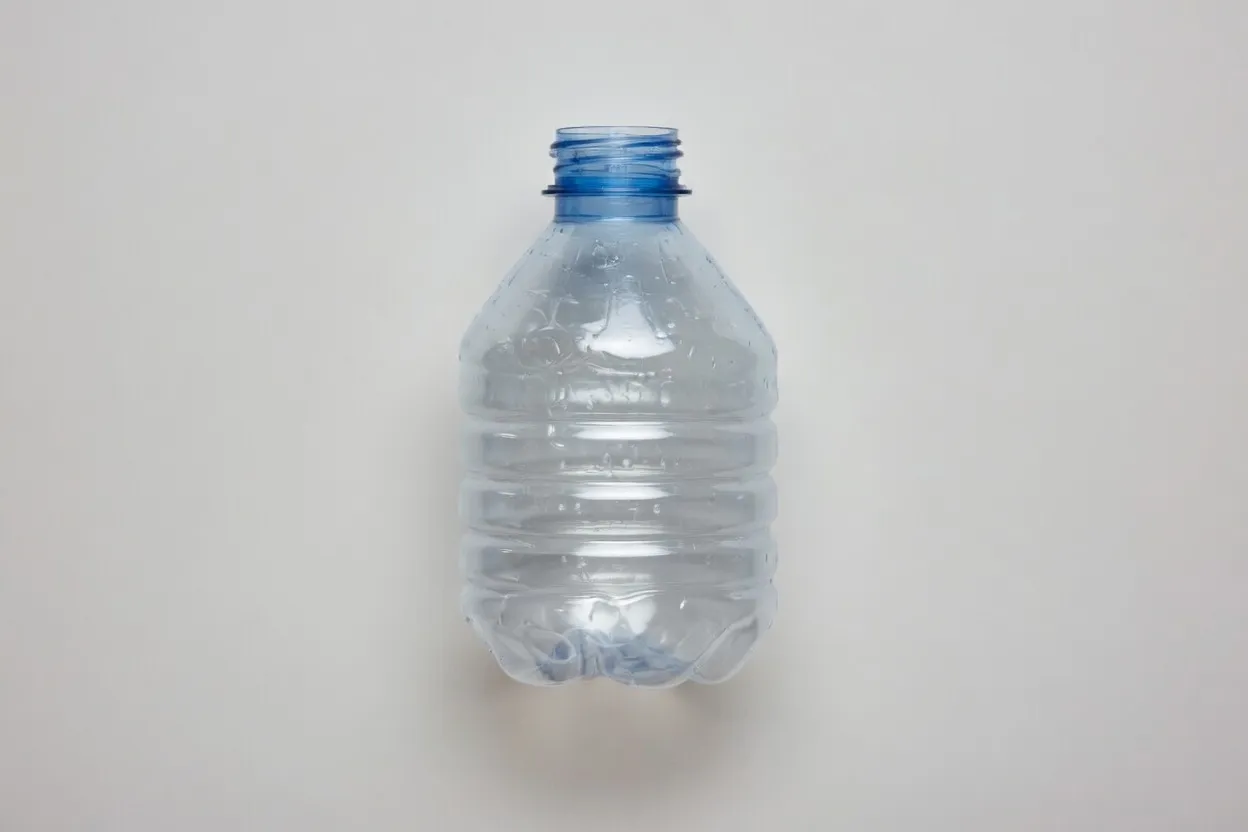
Short Shot — Bottle Doesn’t Fill the Mould Completely
A short shot in the blow stage produces a bottle that fails to achieve full cavity contact — the material does not expand sufficiently to fill the mould, resulting in a truncated shoulder, reduced height, or collapsed top section. Unlike injection short shots, blow-stage short shots are typically consistent across cavities affected by the same pressure or timing setting.
- →High-pressure blow (P2) too low — material cannot reach cavity wall
- →High-pressure blow time too short — pressure not sustained long enough
- →Mould vent slots blocked — trapped air creates back-pressure
- →Preform temperature too low — insufficient material fluidity for expansion
8–12 bar
35–40 bar
≥0.3 s
0.03–0.05 mm
Verify P2 pressure at the mould inlet (not just at the regulator). Line pressure drop can be significant. If inlet pressure is below 33 bar, increase regulator setting and re-measure.
Open the blow mould and inspect vent slots — typically located at the parting line and base insert — for PET residue or tool damage. Clean with ultrasonic bath if contaminated. Confirm slot depth is 0.03–0.05mm.
If pressure and venting are confirmed correct, check preform temperature. Cold preforms require higher pressure to expand. Raise conditioning temperature 3°C and re-test before increasing P2 further.
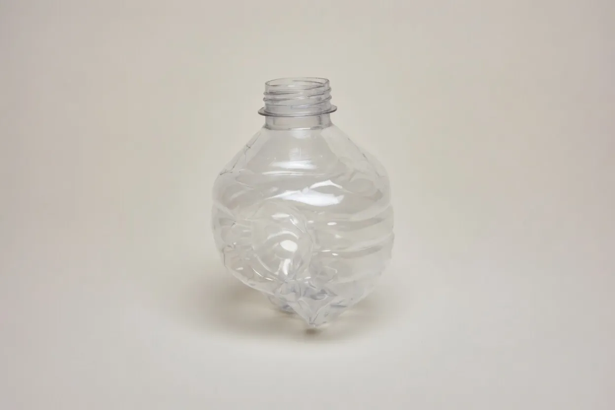
Base Peaking & Rocker Bottom — Bottles That Won’t Stand Upright
Base peaking describes a condition where the bottle base centre is drawn inward excessively, creating a pointed or deeply concave base geometry that prevents stable freestanding. Rocker bottom is a related condition where the base is asymmetric — higher on one side than the other — causing the bottle to rock rather than stand stable. Both are functionally unacceptable for PET bottles destined for filling lines with base-contact conveying.
- →Stretch rod axial velocity too high — over-stretches base material
- →Stretch rod end position too deep — rod contacts base mould insert
- →Pre-blow pressure (P1) too low — base unsupported during axial stretch
- →Preform base wall thickness below design spec (<3.5mm for small bottles)
1.0–1.5 m/s
±0.5 mm
2.5–3.0×
≥3.5 mm
Confirm stretch rod end-stop position against tooling drawing. Use a depth gauge to measure actual rod travel distance from datum. Re-adjust end-stop if outside ±0.5mm of specification.
Reduce stretch rod velocity in 0.1 m/s decrements from current setting. Evaluate base geometry after each adjustment. Target is the lowest velocity that still achieves full body stretch without rocker base.
If rocker bottom is asymmetric (one side higher), check stretch rod alignment — the rod is likely not concentric with the preform axis. This overlaps with the Defect #2 stretch rod inspection procedure.
Top Load Failure — Bottles Collapsing on the Filling Line
Top load strength — the resistance of a bottle to axial compression — is the critical mechanical property for filling line performance. Bottles that fail top load testing will buckle under the weight of capping head pressure, conveyor accumulation, or pallet stacking loads. The minimum requirement for a standard 500ml PET bottle is typically ≥150N, though CSD (carbonated soft drink) applications may specify ≥200N.
Top load strength is almost entirely determined by the degree of biaxial molecular orientation achieved during stretch blowing. A well-oriented PET bottle derives its compressive strength from the molecular network — not from wall thickness. This means reducing weight will not necessarily cause top load failure if orientation is optimised, but poor orientation at any given wall thickness will consistently fail the test.
- →Axial stretch ratio below 2.5× — insufficient chain alignment in vertical axis
- →Hoop (radial) stretch ratio below 3.5× — poor circumferential orientation
- →Blow temperature too high — molecular orientation relaxes before freezing
- →Mould cooling insufficient — material releases from cavity wall too warm
2.5–3.0×
3.5–4.5×
≥10×
≤15°C
Calculate actual axial and hoop stretch ratios from preform dimensions and bottle cavity dimensions. If calculated BUR is below 10×, the preform-to-bottle size ratio is the fundamental design problem — not an adjustable process parameter. Consult the preform engineer.
If calculated BUR is adequate, check mould cooling water temperature and flow rate. Insufficient cooling means bottles demould while still too warm, allowing orientation to partially relax. Target ≤15°C with verified flow rate at each mould circuit.
Verify preform conditioning temperature is not too high. Over-heated preforms have reduced melt strength and lower natural stretch ratio, resulting in under-oriented bottles even at correct stretch parameters.
Sidewall Bubbles & Blisters — Diagnosing Moisture and Contamination
Sidewall bubbles and blisters are among the most serious ISBM defects because they indicate a fundamental material integrity failure. Visible gas voids within the bottle wall are not a cosmetic issue — they represent zones of reduced wall thickness and compromised barrier performance. In pharmaceutical or food-grade applications, this defect triggers immediate product quarantine.
In over 90% of bubble/blister cases, the root cause is PET resin moisture content exceeding 50 ppm at the point of injection. Water hydrolyses the PET ester bonds at processing temperatures (270–295°C), generating CO₂ and acetaldehyde gas. These gases nucleate into bubbles during injection and remain visible in the final bottle. Always check moisture content before adjusting any machine parameter.
- →PET moisture >50 ppm — hydrolytic degradation at melt temperature
- →Drying equipment malfunction — failed desiccant, blocked airflow
- →Barrel temperature above 295°C — thermal degradation of PET chain
- →Resin contamination with foreign polymer or moisture-bearing additive
≤50 ppm
160°C / ≥4h
≤−40°C
≤295°C
Stop production immediately. Take a sample of resin directly from the hopper outlet and perform Karl Fischer moisture analysis. If result exceeds 50 ppm, the resin batch is the confirmed cause.
Inspect drying system: verify desiccant dew point at hopper air inlet is ≤−40°C. If dew point is drifting above −30°C, the desiccant beds are saturated and must be regenerated or replaced before production can restart.
Purge the barrel with dried virgin PET before resuming. Check hopper sealing after extended shutdowns — moisture re-absorption can occur rapidly in humid environments if the hopper lid is left open.
Neck Finish Distortion — Out-of-Spec Thread Dimensions
The neck finish is the only part of the bottle that does not undergo biaxial stretch — it must be dimensionally precise in its injected form and must remain dimensionally stable through the blow stage. Neck distortion manifests as out-of-round thread profiles, vertical dimension changes, or thread pitch variation that causes caps to fail torque or seal specifications.
In single-stage ISBM, the neck zone must be actively cooled and mechanically secured during the blow station. Any excess heat from the injection stage or any clamping insufficiency during blowing creates the conditions for distortion. Because the neck is the precision interface between bottle and closure, tolerances of ±0.1mm or tighter are typical for PCO and 28mm standard finishes.
- →Neck zone receives excessive residual heat from injection stage
- →Neck cooling water circuit blocked or flow rate insufficient
- →Clamping force during blow stage below specification
- →Neck insert wear — precision surfaces worn beyond tolerance
≤10°C (independent)
60–120 kN
≤0.1mm ellipticity
Every 2h on line
Verify neck cooling circuit is independent from the main mould circuit and confirm inlet water temperature is ≤10°C. Measure temperature at circuit outlet — if outlet is significantly warmer than inlet, flow rate is insufficient. Increase cooling water flow to this circuit.
Measure actual clamping force during blow using a calibrated force sensor or confirm machine display matches actual clamp tonnage. Low clamp force allows the neck insert to micro-displace during the P2 pressure phase.
If dimensional issues persist after cooling and clamping corrections, check neck insert wear using precision gauging. Worn inserts must be replaced — they cannot be reworked. Track insert replacement intervals for preventive maintenance scheduling.
ISBM Defect Troubleshooting: Complete Operator Checklist
This four-step sequence should be followed in order for any undiagnosed defect. Working upstream to downstream prevents the common error of adjusting blow parameters to compensate for an injection or material problem — an approach that delays resolution and risks compounding additional defects.
When Process Adjustment Isn’t Enough
The four-step checklist resolves the majority of ISBM defects. However, a subset of recurring or complex failure patterns requires escalation beyond operator-level adjustment. The following conditions indicate that tooling, machine hardware, or process design — rather than parameter settings — are the root cause:
- Defect persists after complete 4-step checklist
- Preform wall eccentricity cannot be corrected by hot runner tuning
- Neck distortion recurs despite cooling and clamp correction
- Gate blush remains after all injection velocity adjustments
- Multiple defects appearing simultaneously on the same cycle
- Top load failure that cannot be resolved by orientation optimisation
- Cycle-to-cycle variability in wall thickness with no identifiable cause
- Temperature control instability across conditioning zones
- Moisture or IV issues confirmed across multiple batches
- Pearlescence occurs despite confirmed correct drying and temperature
- Unexpected colour shift, acetaldehyde odour, or rapid IV degradation
- New resin grade transition requiring process window redetermination
ISBM Solution’s engineering team can provide process simulation, defect risk analysis, and application-specific parameter recommendations before machine selection — reducing commissioning time and defect-related waste from day one.